PIPING-KNOWLEDGE has useful guide for piping engineers. including piping layout , piping supports , codes and standards, software learning like aveva E3d , Pdms , Caesar II. site contain different piping layout .It also content video animations of valves and oil and gas refining process.site has overal piping engineering guide which is useful for piping engineer.

Flare System & its Requirements Gas flaring is a combustion device to burn associated, unwanted or excess gases and liquids released dur...


Flare System & its Requirements

Gas flaring is a combustion device to burn associated, unwanted or excess gases and liquids released during normal or unplanned over-pressuring operation in many industrial processes, such as oil-gas extraction, refineries, chemical plants, coal industry and landfills.


Flare systems provide for the safe disposal of gaseous wastes. Depending on local environmental constraints, these systems can be used for:

1) Extensive venting during start up or shutdown
2) Venting of excess process plant gas
3) Handling emergency releases from safety valves, blow-down, and depressuring        systems

- Design will vary considerably, depending on the type of connected equipment and complexity of overall system. A flare system generally consists of an elevated stack, means to maintain burning conditions at the top of stack.

- Whenever industrial plant equipment items are over pressurized, the pressure relief valves provided as essential safety devices on the equipment automatically release gases and sometimes liquids. Those pressure relief valves are required by industrial design codes and standards, as well as by law.

 - The released gases and liquids are routed through large piping systems called flare headers, to a vertical elevated flare. The released gases are burned as they exit the flare stacks. The size and brightness of the resulting flame depend on the flammable material’s flow rate in terms of joules per hour.

Working of flare system:


Based on height of flare tip, flares can be categorized into two types:
Ground flare:
1) Open ground flare
2) Enclosed ground flare
Elevated flare:
1) Self supported flare
2) Derrick supported flare
3) Guyed stack flare


Types of flare based on mixing at flare tip:
1) Steam assisted flares
2) Air assisted flares
3) Pressure assisted flare
4) Non-assisted flare

Ground Flare:
A Ground Flare is where the combustion takes place at ground level. It varies in complexity and may consist either of conventional flare burners discharging horizontally with no enclosure or of multiple burners in refractory-lined steel enclosures. Ground flares is the preferred choice only if plant is located in an area where it is highly desirable to have a flare which is not visible in public.

Open Ground Flares:
Here Flare Headers distribute and the flaring occurs at ground, with the area surrounded by radiation fences. Most have multiple burners that combine to flare large amounts of gas. The burners are located either in a refractory lined enclosure or in a pit. Open ground flare can combust large quality than enclosed flares. Another type of ground flares is the horizontal flare which is located in an open pit.


Enclosed ground flares:
Enclosed ground flares are the most practical ground flare type for industries located in city areas. While they are expensive, they provide a means of smokeless combustion without a flame visible to the surrounding area. Hot combustion gases from an enclosed ground flare are discharge to the atmosphere through an opening at the top of the refractory lined enclosure.


Elevated Flares:

For safety reasons it’s a advantage to have flares at considerable height from ground. Elevated flares are preferred over enclosed ground flares due to lower costs. Elevated flares are also preferred over open pit ground flares due to lower land requirements.

Self-supported flares:
The self-supporting stack is a freestanding stack anchored to a base Self-supported flare system is used for lower heights when radiation exerted is low. It uses less space for installation. Self-supporting flares are generally used for lower flares tower heights 9mtr to 30mtr but can be designed for up to 75mtr.


Derrick supported flares:
The derrick supported stack is located in the centre of a derrick structure and is held to the structure by tie rods and guides. Derrick supported flares can be built to a considerable height since the system load is spread over the derrick structure. Derrick supported flare system is optimum installation for higher heights where high radiation is exerted. Derrick supported flares are the most expensive design for a given flare height. The derrick supported stacks have been built for around 120mtr Height.


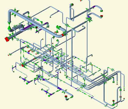
Flare gas transportation Piping:
Waste gases from vents, blowdown gases released from pressure relief devices are sent to the flare stack through the gas collection header. This piping should be designed to have minimum pressure drop. Potential dead legs and liquid traps are avoided. Use of valves in this line should be kept to minimum and when used should be sealed to open position. The piping should be equipped for purging so that explosive mixtures do not occur in the flare system either on start up or during operation. Minimum slope of the flare header shall be 1:450 (as per API 521).

Vessels & Drums used in Flare system:
Mainly four type of vessels or drums used in design of flare system:
1) Knockout drum    
2) Blowdown drum         
3) Quench drum          
4) Seal drum        

Knockout Drum:
Liquid present in the vent stream or liquid that may be condense out in collection header and transfer lines are removed by the Knockout drum. The knockout drum may be horizontal or vertical type.

A knockout drum is required where enough hydrocarbon liquids are entrained with or condensed from gas to avoid possible fire hazards from liquid droplets falling out of the flare. The function may be combined with that of blowdown drum to provide a single drum, where small quantities of liquid are involved.

The knockout drum may be either horizontal or vertical. Horizontal drums are more common for large relief loads for the following reasons:

-The required elevation of the relief header is lower than for a vertical drum.

-The horizontal drum would cost less than the vertical drum which has equivalent capacity.

Blowdown drum:

Blowdown drum is used when sizable liquid releases from process is required to be captured. The releases may be intentional like drainage from liquid drain system during shutdown or start up- or emergency vents of PSV discharge. The drum may be capable of accepting the anticipated liquid loads without filling beyond maximum operating level of drum. This maximum operating level must provide a gas flow path with sufficiently low gas velocity to allow gravity separation and prevent re-entrainment beyond design droplet size. Blowdown drums is located near sources, close to battery limits of a process unit or area to reduce to reduce amount of piping subject to two phase slug flow.

Quench drum:

A quench drum can be used to condense vapour discharge from relief device for either later return into the process after relieving condition has passed or for disposal to sewer. Generally a Quench drum is provided whenever the material being relieved is too valuable to be burned in a flare or too toxic to be relieved to atmosphere. A Quench drum can be used to cool hot material so that the entire relief system does not need to be designed for higher temperature. Other purpose for quench drum is to quench runaway reactions.


<< READ OTHER INTERESTING POST >>


     DISTILLATION COLUMN PIPING


       READ MORE >> 


 PIPE RACK PIPING


       READ POST >>


   PIPING SUPPORTS


  READ MORE >>


EXPANSION LOOP CALCULATION


 READ MORE >>


   CHECKLIST FOR PIPING ISOMETRIC

    READ POST >>


     TYPES OF GASKET


        READ POST >>


Pipe Wall Thickness calculation

    READ MORE >>


    TYPES OF FLANGES

     READ MORE >>


TYPES OF STORAGE TANK

     READ POST >>


HEAT EXCHANGER 


READ POST >>


 TYPES OF PUMP


READ POST >>


PUMP PIPING


 PIPING MATERIAL


        READ MORE >>


           TYPES OF VALVES


           READ MORE >>


    PUMP PIPING


          READ MORE >>


 HEAT EXCHANGER


READ POST >>


 TYPES OF PUMP


READ POST >>


TYPES OF DISTILLATION  COLUMN

READ POST >>


 PDMS & E3D COMMANDS

      READ POST >>


     Caesar II Tutorials            

 READ POST >>


     COMPRESSOR PIPING

    READ MORE >>


     PIPE RACK PIPING


        READ POST >>


    Aveva E3D Tutorials

    READ POST 


      UNDERGROUND PIPING


      READ POST >>


  Importance of Pump Alignment: Power is transmitted from a motor to a pump by connecting the motor and pump shafts. They can be directly co...


Importance of Pump Alignment:


  1. Power is transmitted from a motor to a pump by connecting the motor and pump shafts. They can be directly connected using a straight shaft or joined together by a flexible coupling. In some systems, belts are also used between the motor and the pump or the motor and the coupling.
  2. Misaligned shafts lead to costly and unplanned downtime. They also often result in damaged seals. Consequently, broken seals can cause lubrication problems and leaks. 


Misalignment can occur in three ways

  1.    Radial (offset or parallel) misalignment :
       The centerlines of the two shafts are parallel but offset.
  2.    Axial (or end float) misalignment :
       The two shafts are aligned but one (or both) axles are prone to in/out               movement along the centerline
  3.    Angular misalignment :
       The centerlines of the two shafts are not parallel.

  • Shaft misalignment occurs when the shaft or surface is dislocated from its ideal position. Misalignment is the deviation in the shaft position when the pump is operating at standard conditions. Misalignment can lead to troubles in either a section of the pump or its entirety. Misalignment is a problem even for pumps with flexible couplings. Though a flexible coupling has more room for movement than a standard coupling, it can only function with small misalignment.

Types of shaft Alignment methods:

  • Visual Line-Up
  • Straightedge/Feeler Gauge
  • Rim and Face
  • Cross Dial
  • Reverse Dial
  • Laser

How are Pumps and Motors Secured?

  • To maintain good alignment, it is important to minimize vibrations by securing the pumping system to sound foundations. Industrial pumps are normally bolted directly to a machined baseplate and other equipment is aligned and secured to it. The entire assembly is sited on a concrete foundation and affixed with epoxy or cement grouting. When constructed properly, overall vibrations can be substantially reduced because of the damping effect of the foundation mass. As a general rule, foundations should be at least three times the mass of the pumping system for centrifugal pumps and five times for reciprocating pumps.

Misalignment in pumps can lead to several troubles like:

  • Seal failure
  • Bearing Failure
  • Increase in Energy Consumption
  • Excessive Heat Generation
  • Increased Vibration
Hence, one must detect the signs of misalignment as soon as it occurs to prevent the catastrophic failure of the pump.

Common Causes of Misalignment :

Shaft and belt misalignment can be a result of several factors such as:

  • Soft foot is a condition in which one of the feet of a pump does not sit flat on the baseplate. Soft foot is among the most common causes of misalignment. To check, operators should first assess the equipment’s foundation and employ a suitable shaft alignment tool to identify and correct potential soft foot conditions. Some laser-guided alignment tools have a soft foot operation capability that guides the operators through corrective procedures. 
  • Bearings out of square with their housings are another common cause of misalignment. Often a condition of wear, the out-of-square bearing and/or its housing will need to be corrected or replaced to bring pumps back into alignment.

Other possible causes include:

  • Poor pump and motor alignment during instalment
  • Worn out components
  • Excessive forces generated by attachments
  • Foot locator has moved or warped
  • Thermal expansion
  • Excessive forces and moments

What is Thermal Growth?

  • During operation at temperature, expansion of the drive shaft and other pump components can affect a pump’s alignment. This effect is called thermal growth and must be taken into account when selecting and fitting a shaft coupling and when correcting shaft alignment.

How can Misalignment Problems be Detected?

  • Noise and vibrations can be the first indications of problems with a running pumping system. Vibrational analysis, performed as part of a preventative maintenance and monitoring programmed, can identify if shaft misalignment is becoming a problem. The diagnosis for shaft misalignment is indicated by abnormally high vibration levels at one and/or two times the shaft rotational rate frequency. Rapid identification of misalignment in this way can save a pumping system from damage.


       << READ OTHER INTERESTING POST >>


   PIPING SUPPORTS


  READ MORE >>


EXPANSION LOOP CALCULATION


 READ MORE >>


     DISTILLATION COLUMN PIPING


       READ MORE >> 


   CHECKLIST FOR PIPING ISOMETRIC

    READ POST >>


 PIPE RACK PIPING


       READ POST >>


     TYPES OF GASKET


        READ POST >>


        OIL & GAS PROCESS


       READ POST >>


Pipe Wall Thickness calculation

    READ MORE >>


    TYPES OF FLANGES

     READ MORE >>


 HEAT EXCHANGER


 READ POST >>


 TYPES OF PUMP


READ POST >>


  Globe Valve Globe valves may be used for isolation and throttling services. Although these valves exhibit slightly higher pressure drops t...

 Globe Valve

Globe valves may be used for isolation and throttling services. Although these valves exhibit slightly higher pressure drops than straight through valves they may be used where the pressure drop through the valve is not a controlling factor.  Globe valves are extensively employed to control flow. The range of flow control, pressure drop, and duty must be considered in the design of the valve  to assure satisfactory service and to avert premature failure Valves subjected to high-differential pressure-throttling service require specially designed valve trim .Generally the maximum differential pressure across the valve disc should not exceed 20 percent of the maximum upstream pressure or 200 psi (1380 kPa), whichever is less. Valves with special trim may be designed for applications exceeding these differential pressure limits.


Types of Globe Valves

1) Tee Pattern globe valves have the lowest coefficient of flow and higher pressure drop. They are used in severe throttling services, such as in bypass lines around a control valve. Tee-pattern globe valves may also be used in applications where pressure drop is not a concern and throttling is required.


2) Wye Pattern globe valves, among globe valves, offer the least resistance to flow. They can be cracked open for long periods without severe erosion. They are extensively used for throttling during seasonal or startup operations. They can be rod through to remove debris when used in drain lines that are normally closed.


3) Angle Pattern globe valves turns the flow direction by 90 degrees without the use of an elbow and one extra weld. They have a slightly lower coefficient of flow than wye-pattern globe valves. They are used in applications that have periods of pulsating flow because of their capability to handle the slugging effect of this type of flow.


Construction of a Globe Valve

Globe valves usually have rising stems, and the larger sizes are of the outside screw-and-yoke construction. Components of the globe valve are similar to those of the gate valve. This type of valve has seats in a plane parallel or inclined to the line of flow.

Maintenance of globe valves is relatively easy, as the discs and seats are readily refurbished or replaced. This makes globe valves particularly suitable for services which require frequent valve maintenance. Where valves are operated manually, the shorter disc travel offers advantages in saving operator time, especially if the valves are adjusted frequently. The principal variation in globe-valve design is in the types of discs employed. Plug-type discs have a long, tapered configuration with a wide bearing surface. This type of seat provides maximum resistance to the erosive action of the fluid stream. In the composition disc, the disc has a flat face that is pressed against the seat opening like a cap. This type of seat arrangement is not as suitable for high differential pressure throttling.

 The conventional disc, in contrast to the plug type, provides a thin contact between the taper of the conventional seat and the face of the disc. This narrow contact area tends to break down hard deposits that may form on the seats and facilitates pressure-tight closure. This arrangement allows for good seating and moderate throttling.

Advantages of a Globe Valve

1. Good shutoff capability

2. Moderate to good throttling capability

3. Shorter stroke (compared to a gate valve)

4. Available in tee, wye, and angle patterns, each offering unique capabilities

5. Easy to machine or resurface the seats

6. With disc not attached to the stem, valve can be used as a stop-check valve.


Disadvantages of a Globe Valve

1. Higher pressure drop (compared to a gate valve)

2. Requires greater force or a larger actuator to seat the valve (with pressure under the seat)

3. Throttling flow under the seat and shutoff flow over the seat


       << READ OTHER INTERESTING POST >>


   PIPING SUPPORTS


  READ MORE >>


EXPANSION LOOP CALCULATION


 READ MORE >>


     DISTILLATION COLUMN PIPING


       READ MORE >> 


 PIPE RACK PIPING


       READ POST >>


     TYPES OF GASKET


        READ POST >>


        OIL & GAS PROCESS


       READ POST >>

 HEAT EXCHANGER


READ POST >>


 TYPES OF PUMP


READ POST >>


TYPES OF DISTILLATION  COLUMN

READ POST >>


 PDMS & E3D COMMANDS

      READ POST >>


     Caesar II Tutorials            

 READ POST >>


     COMPRESSOR PIPING

    READ MORE >>


     PIPE RACK PIPING


        READ POST >>


    Aveva E3D Tutorials

    READ POST 


      UNDERGROUND PIPING


      READ POST >>