PURPOSE :
A pipe support is a designed element that transfer the load from a pipe to the supporting structures. The load includes the weight of the pipe proper, the content that the pipe carries, all the pipe fittings attached to pipe, and the pipe covering such as insulation. The four main functions of a pipe support are to anchor, guide, absorb shock, and support a specified load. Pipe supports used in high or low temperature applications may contain insulation materials. The overall design configuration of a pipe support assembly is dependent on the loading and operating conditions.
As per general detail the support is classified as:
1. Primary Supports:
It is the parts of support assembly which is directly connected to the pipe.
It is the parts of support assembly which is directly connected to the foundation / structure and is supporting the primary support attached to the pipe line.
2. Pipe Supports Classification as per Construction:
Based on construction details, pipe supports are broadly classified in three types, as
– RIGID SUPPORTS
– SPRING SUPPORTS
– ADJUSTABLE SUPPORTS
These are described below in brief.
Rigid Supports:
This type of support arrangement is generally very simple and has maximum use in piping. It does not have adjustability to the erection tolerances. It will directly rest on foundation or structure which is supporting the pipe. Common type of RIGID SUPPORTS are shoe type (welded), shoe type (with clamp) Trunnion type, valve holder type, support brackets (Secondary Support). These are described under the topic ‘Supports Generally used’.
Rigid pipe supports restrict movement in at least one direction. This support system directly rests on the foundation that is supporting the pipe. It cannot be adjusted to suit construction or installation tolerances.
Pipe Guides (Cylinder Pipe Guides - Spider Guides)

Rigid supports are used to restrict pipe in certain direction(s) without any flexibility (in that direction). Main function of a rigid support can be Anchor, Rest, Guide or both Rest & Guide.
1) Stanchion/Pipe Shoe:
Rigid support can be provided either from bottom or top. In case of bottom supports generally a stanchion or Pipe Clamp Base is used. It can be simply kept on steel structure for only rest type supports. To simultaneously restrict in another direction separate plate or Lift up Lug can be used. A pipe anchor is a rigid support that restricts movement in all three orthogonal directions and all three rotational directions, i.e. restricting al the 6 degrees of freedom This usually is a welded stanchion that is welded or bolted to steel or concrete. In case of anchor which is bolted to concrete, a special type of bolt is required called Anchor Bolt, which is used to hold the support with concrete. In this type of support, normal force and friction force can become significant. To alleviate the frictional effect Graphite Pad or PTFE plates are used when required.
SHOE SUPPORT

TRUNNION SUPPORT


CLAMP SHOE SUPPORT


CRYOGENIC SERVICE SUPPORT


2) Rod Hanger:
It is a static restraint i.e.it is designed to withstand tensile load only (no compression load should be exerted on it, in such case buckling may take place). It is rigid vertical type support provide from top only. It consists of clamp, eye nut, tie rod, beam attachment. Selection of rod hanger depends on pipe size, load, temperature, insulation, assembly length etc. As it comes with hinge and clamp, no substantial frictional force comes into play.


3) Rigid Strut:
It is a dynamic component i.e. designed to withstand both tensile and compression load. strut can be provide in vertical as well as horizontal direction. V-type Strut can be used to restrict 2 degrees of freedom. It consists of stiff clamp, rigid strut, welding clevis. Selection depends on pipe size, load, temperature, insulation, assembly length. As it comes with hinge and clamp, no substantial frictional force comes into play.


2.2 Spring Supports:
- Any line operating at high temperature moves upwards/downwards (depending on the pipe configuration) due to thermal expansion. Any rigid support provided on such a line tends to lift pipe up/down and hence remain inactive during operating conditions. In such a case a flexible support (springs) is provided which is capable of taking the load in all the operating and cold conditions.
- The spring supports provides continuous support during expansion or contraction of the pipe.
- The spring support basically employs a spring element, which can get compressed or stretch-out depending upon the thermal movement of pipe and the corresponding loads.
Types of Spring Supports
Depending on the loads to be accommodated and the magnitude & direction of the thermal displacement to be supported, spring supports are broadly classified as:
- Variable effort springs
- Constant effort springs
Some of the common terminology associated with the selection and procurement of any Springs are listed below:
- Cold Load
- Hot Load
- Spring Rate
- Spring Travel
- Load Variation or Variation
- Pre-compression Length
Variable and Constant Springs
Both types of spring are pre-compressed so that they exert a specified upward force on the pipe. Ideally this force is equal to the weight of the pipe (plus contents) the spring is intended to support, thus imposing minimum weight loading on adjacent supports or equipment. The difference is that as the pipe moves from the installed to the operating position the force exerted by a variable spring alters as the compression on the coils is either increased or reduced where as that of constant unit remains virtually unaltered
Variable springs are preferred to constant on economic grounds, being cheaper by a factor of between 2 and 3 than an equivalent constant unit. Generally variability at spring adjacent to strain sensitive equipment such as pumps, compressor and turbines is limited to 20%. Where a suitable variable spring cannot be specified, a constant unit is used.
Location of spring supports
Spring supports specified during the flexibility review are located on the Stress Sketches and it is the Pipe Support Designer's responsibility to reflect this in the design. Generally spring locations are governed by practical considerations such as the location of steelwork rather than optimum support positions. However, special structures may be erected for specific purposes eg. spring supports directly above top discharge nozzle of pumps.
Spring Deflections
Variable springs are rated for deflections applying to normal operating conditions. Additionally, the spring travel must be sufficient to cater for all other expansion conditions (design, start-up, shut-down etc). The spring variability for these conditions is reviewed and the springs selected so that excessive loading on adjacent nozzles is avoided.
VARIABLE SPRING SUPPORT


Adjustable Supports:
This type of support is Rigid type in construction but is has few nuts and bolts arrangements for adjusting the supports with respect to the actual erected condition of pipe. The support can be adjusted for the erection tolerances in the piping. These are required for a better supporting need at critical locations of pipe supports.
Mostly all type of rigid supports can be modified by using certain type of nuts and bolts arrangement, to make it as an Adjustable support.
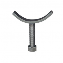
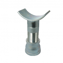
192 Adjustable Pipe Saddle
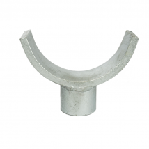
521 Adjustable Pipe Saddle Support w/ Coupling
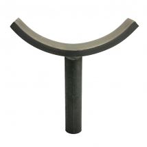
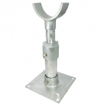
520 Pipe Saddle Support
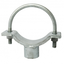
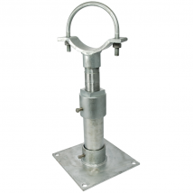
525 Adjustable Pipe Saddle Support w/ U-Bolt
526 Adjustable Pipe Saddle Support
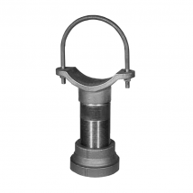
527 Adjustable Pipe Saddle Support w/ U-Bolt
528KT Adjustable Support Kit
INSULATED PIPE SUPPORTS
Insulated pipe supports are designed to prevent direct heat transfer between pipes and their supports. Thus, they reduce heat loss due to conduction at each support. They serve the following purposes: Carry the load and allow necessary movement at each suppose point, provide insulation in the support area where the regular pipe insulation cannot be installed and minimize the cost of field installation by reducing installation time. The supports are not welded to the pipe and each unit is shipped completely assembled (except for the riser supports and anchor supports, both of which require some welding).


GRE pipe support design
Pipe support design for fiberglass piping follows the same same fundamentals as other metallic piping. Supports are designed to limit the deflection and allowable stresses within the design limits. Manufacturers recommendation are to be followed for supporting fiberglass piping.
Fiberglass reinforced pipe is an anisotropic composite material which results in different modulus values in tensile, bending and compression. The modulus varies again depending upon type of resin, amount of glass, and reinforcement orientation used. Care must be taken to ensure that the appropriate modulus is used, which should come from the manufacturer.
Fiberglass piping does not have the same outside diameter as steel piping. This requires the support components such as clamped shoes, U-bolts etc. to be customized for fiberglass piping. The thermal expansion of fiberglass piping is two to five times that of steel. Additionally the axial expansion due to internal pressure can be significant for fiberglass piping. However, note that the loads due to pressure expansion apply only at direction changes.
General Guidelines for Supporting
For supporting fiberglass piping systems, the following general guidelines should be given due consideration:
- Fiberglass piping should not be supported directly on steel structure.
- Supports should be designed to avoid point loads on the fiberglass piping.
- Supports must be stiff enough to prevent pipe deformation.
- Support components must be sized to properly fit the pipe.
- In-line equipment should be independently supported.
- Supports should not be located on pipe joints.
- Pipe shall be protected against abrasion at support locations.
The supports are also classified as per function are further described as follows:
1. Loose Support:
This is most commonly used support meant for supporting only the pipe weight vertically. It allows pipe to move in axial as well as transverse direction but restricts only the vertical downward movement.
2. Longitudinal Guide:
This type of support is used to restrict the movement of pipe in transverse direction i.e. perpendicular to length of pipe but allow movement in longitudinal direction. This is also a commonly used type of support. Generally it is used along with Loose support.
3. Transverse Guide:
This type of support is used to restrict the movement of pipe in longitudinal (axial) direction but allows the pipe to move in transverse direction. This is also referred as ‘AXIAL STOP’. This type is less used as compared to above two types. Generally it is used along with Loose support.
4. Fixed point/Anchor:
FIX POINT type of support is used to restrict movements in all three directions. ANCHOR type of support is used to restrict movement in all three directions and rotation also in these three directions.
Non-Welded Type (Fix Point):
This can be considered as a combination of longitudinal and transverse guide. This type resists only the linear movements in all directions but not the rotational movements. This avoids heavy loading of support as well as pipe. Therefore this type of support is preferred over welded type.
Welded Type (Anchor)
This type of support prevents total movements i.e. linear as well as rotational. This type of support is used when it is absolutely essential to prevent any moment/force being transferred further. It causes heavy loading on support as well as pipe.
5. Limit Stop:
As name itself indicates it allows pipe movement freely upto a certain limit and restricts any further movement. This is useful when total stops causes excessive loading on piping and support or nozzle.
This type of support should be used selectively, because of stringent and complicated requirements of design, erection and operation.
6. Special Supports:
When we need a pipe support whose construction or functional details are different from the available details, then a special support detail sketch is prepared. The functions of this support can be any combination of above functions.
Selection of Pipe Supports: Parameters Considered
The basic parameters considered during the selection of supports are mentioned below:
1) Process design conditions
2) Pipe material of construction
3) Piping Loads including Piping weight, fluid,weight, Valves,inline instruments etc.
4) Insulation material,thickness,density & specification.
5) Piping General Arrangement drawing
6) Thermal forces,moments & displacement of Piping
7) Occasional loads: Hydrotest loads, Sesimic loads, wind loads etc.
As per clause 321.1.1 of code ASME B31.1, the objective of support design is as below:
The layout and the design of the piping and its supporting elements shall be directed towards preventing the following
1. Piping stresses in excess of those permitted in the code.
2. Leakage at joints.
3. Excessive thrust and moments on connected equipment (such as pumps and turbine).
4. Excessive stresses in the supporting (or restraining) elements.
5. Resonance with impose fluid induced vibrations.
6. Excessive interference with thermal expansion and contraction in a piping system, which is otherwise adequately flexible.
7. Unintentional disengagement of piping from its supports.
8. Excessive piping sag in systems requiring drainage slope.
9. Excessive distortion or rag of piping (e.g. thermo plastics) subject to creep under conditions of repeated thermal cycling.
10. Excessive heat flow, exposing supporting elements to temperature extremes outside their design limits.
Considering the above criteria, piping supports shall be selected and designed.
The basic type of supports used in refinery are:
Anchors: It restricts all six degree of freedom (i.e,Rotational, Longitudinal & Axial).
Guides: It restricts the longitudinal movements but free to move in rotational and axial.
Line Stops: It restricts the axial movements but free to move in rotational and longitudinal.
Rests: It takes the vertical loads generated due to pipe weight, fluid weight,thermal loads and occasional loads
SUPPORT SPAN :

NOTE: Support span may vary with following criteria
1. Material of pipe
2. Fluid service
3. Loads on piping
4. Piping Layout
5. Insulation load


0 Comments: