DISTILLATION COLUMN
Distillation is the most important separation process in the petroleum and chemical industries. It is the separation of key components in a mixture by the difference in their relative volatility, or boiling points. It is also known as fractional distillation or fractionation.

Distillation columns (distillation towers) are made up of several components, each of which is used either to transfer heat energy or enhance material transfer. A typical distillation column consists of several major parts:
- •
A vertical shell where separation of the components is carried out.
- •
Column internals such as trays, or plates, or packings that are used to enhance component separation.
- •
A reboiler to provide the necessary vaporization for the distillation process.
- •
A condenser to cool and condense the vapor leaving the top of the column.
- •
A reflux drum to hold the condensed vapor from the top of the column so that liquid (reflux) can be recycled back to the column.
DISTILLATION COLUMN WORKING PROCESS WATCH VIDEO
There are two main categories of distillation columns, batch and continuous.
1) Batch distillationBatch refers to a distillation setup where there is one tank (called a boiler, just a tank with a heat source) which will be filled with a finite amount of material to be distilled and then closed shut. The liquid will be heated, the more volatile product will be collected in a more concentrated form out the top of the column, and the material left in the boiler contains less of the more volatile product. Batch distillation is what chemical engineers describe as a non-steady state process. This is because the concentration of the more volatile product in the boiler is constantly dropping. In order to maintain a constant purity of product, parameters need to be changed during the run (increase in reflux ratio), or else the purity of the product will keep dropping.
This is usually the way microdistilleries in Australia and the rest of the world make vodka, whisky, gin, rum etc.
Batch distillation allows products with different boiling points to
come off the still sort of in an orderly fashion. It isn’t quite this
simple, but it can be thought of that compounds with lower boiling
points will come off first. This allows the separation of heads, hearts
and tails cuts. The distiller can select which cuts to put into the
finished product.2) Continuous distillation
Continuous distillation systems can run 24/7 without ever stopping to refill the boiler tank. Liquid called the “feed” which is a mixture of two or more liquids to be separated (e.g. alcohol and water) is pumped constantly into a distillation column. The more volatile alcohol will be collected out the top of the column, and the higher boiling point water will make its way to the bottom of the column. Continuous distillation capable of incredibly high throughput, industrial ethanol plants can make millions of litres of ethanol a day using this method without ever
stopping.Continuous distillation systems are much more energy efficient. The waste boiling water out of the bottom of the distillation column can be pumped past the incoming 7% alcohol feed using a heat exchanger to recover most of the energy. A simple heat exchanger is a pipe inside a pipe. One liquid flows through the inside pipe and the other through the outside pipe. The hotter liquid heats up the other liquid. Hence, most of the energy used to boil the water can be recovered by preheating the feed.

PIPING DESIGN CONSIDERATION FOR DISTILLATION COLUMN READ MORE>>
Types of column internals
The tray column typically combines the open flow channel with weirs, downcomers, & Heat exchanger.Free surface flow over the tray is disturbed by gas bubbles coming through the perforated tray with possible leakage of liquid dropping through the upper tray.
Usually, trays are horizontal, flat, specially prefabricated metal sheets, which are placed at a regular distance in a vertical, cylindrical column. Trays have two main parts: (1) the part where vapor (gas) and liquid are being contacted – the contacting area and (2) the part where vapor and liquid are separated, after having been in contact – the downcomer area.
Classification of trays is based on:
- 1.
The type of plate used in the contacting area.
- 2.
The type and number of downcomers making up the downcomer area.
- 3.
The direction and path of the liquid flowing across the contacting area of the tray.
- 4.
The vapor (gas) flow direction through the plate.
- 5.
The presence of baffles, packing or other additions to the contacting area to improve the separation performance of the tray.
Common plate types, for use in the contacting area are:
- 1.
Bubble cap trays, in which caps are mounted over risers fixed on the plate (Figure 4.5). The caps come in a wide variety of sizes and shapes, round, square, and rectangular (tunnel).
- 2.
Sieve trays, which come with different hole shapes (round, square, triangular, rectangular (slots), star), various hole sizes (from about 2 mm to about 25 mm) and several punch patterns (triangular, square, rectangular).
- 3.
Valve trays that are also available in a variety of valve shapes (round, square, rectangular, triangular), sizes, weights (light and heavy), orifice sizes and either as fixed or floating valves.
Trays usually have one or more downcomers. The type and number used mainly depends on the amount of downcomer area required to handle the liquid flow. Single pass trays are those which have one downcomer delivering the liquid from the tray above. This is a single bubbling area across which the liquid passes to contact the vapor and one downcomer for the liquid to pass to the tray below.
Trays with multiple downcomers, and hence multiple liquid passes, can have a number of layout geometries. The downcomers may extend in parallel from wall to wall, or they may be rotated by 90 or 180 degrees on successive trays. The downcomer layout pattern determines the liquid flow path arrangement and liquid flow direction in the contacting area of the trays.
Giving a preferential direction to the vapor flowing through the orifices in the plate will induce the liquid to flow in the same direction. In this way, liquid flow rate and flow direction, as well as liquid height, can be manipulated. The presence of baffles, screen mesh or demister mats, loose or restrained dumped packing and/or the addition of other devices in the contacting area can be beneficial for improving the contacting performance of the tray, and hence its separation efficiency.
Reflux, the liquid fed back into the top of the column needs to mix intimately with the rising vapours. If the reflux is simply running down the walls of the distillation column and the vapours are rising up the inside without mixing, there will be very little purification taking place. The column internals are designed to mix the reflux with the rising vapour.
All of these column internals can be used in either batch or continuous mode. It should also be mentioned that a pot still, one used to make whisky and flavour gin, is a type of distillation system without any column internals. A pot still is the simplest type of still and consists basically of just a boiler and condenser.
Bubble caps

Bubble caps are a type of distillation column internal which forms a positive vapour seal at each plate. Distillation columns can contain as little as 1 of these plates to 30+. The more plates, the higher purity the product will be. The alcohol flowing down the column, called the reflux, will form a pool of liquid on each plate. Alcohol vapour will flow up from the plate below, through the inside of the little round cap and bubble into the pool of liquid on the tray, mixing the vapour and liquid intimately. Each bubble plate has a downcomer, in the picture above you can see a drain hole, this is it. Liquid can only pool up on the plate as high as the downcomer, all excess liquid will flow down to the next plate. Bubble cap plates are excellent for alcohol distillation, but have a some drawbacks. They are expensive. They can’t handle much suspended solids in the column, in the case of continuous distillation where the feed is pumped into the column. In alcohol production, milled grain husks can still be present in the alcohol to be distilled. Sieve tray column internals can handle solids without the need to filter, where bubble caps and random packing will quickly clog up.
Sieve trays

Sieve trays are basically a metal plate with a bunch of holes cut in them, like a sieve, also called a perforated plate. Part of the plate is cut away so that liquid can flow down the column. Sieve trays are very cheap and simple, can handle solids and are very efficient. However, they can only operate in a small flow rate range. If you don’t have the reflux and upcoming vapour rate perfectly calculated the sieve tray won’t work very well at all. If the reflux isn’t high enough, the plate
won’t have a liquid seal and the rising vapour will simply shoot up the column without being mixed. Microdistilleries hardly ever use sieve trays for this reason, choosing to use the more expensive bubble cap option, which has a liquid seal at each plate by design, a more foolproof option. Large petrochemical plants have teams of engineers designing their column, so often choose sieve trays over bubble caps.Valve trays

Similar to a bubble cap plate, but instead of a solid cap with slots in it, a moveable riser sits in place of the bubble cap. Once the pressure beneath the riser (valve) reaches a certain level, the riser lifts up and the vapours mix with the liquid on the tray. Valve trays are sort of a cross between a sieve tray and a bubble cap plate. They are cheaper than bubble caps in industrial installations, provide great throughput and efficiency, but can’t run at the same range of flow rates that bubble cap plates can.
Random packing
Instead of having discrete plates inside a column, you can simply pour a bunch of tiny metal, ceramic or plastic pieces into the column. The reflux will flow down the pieces and mix with the rising vapours.
In a properly designed randomly packed column, greater separation can be obtained vs bubble caps, valve trays of sieve trays in the same column height.
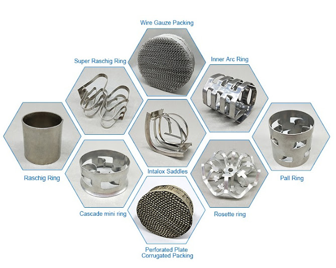
Usually the random packing is small metal rings. Types include Pall Rings, Dixon Rings, Raschig Ring and Super Raschig Ring.
You can’t simply pour random packing rings into a column and expect it to work well though. If reflux is running down the walls of the column, vapours won’t be mixing with it and little separation will occur. Random packing columns need a plate called a distribution plate or distributor every so often down the column, to ensure reflux is running evenly over all the packed rings and not down the walls. The distribution plate is generally just a perforated metal plate with central holes.
Structured packing
Structured packing is like a porous piece of metal honeycomb with channels designed in it to flow reflux down the column. They are more expensive than random packing, but can often have higher efficiency than random packing and less pressure drop.

PIPING DESIGN CONSIDERATION FOR DISTILLATION COLUMN READ MORE>>
2) Continuous distillation


Nice And useful blog Check Out This One Stainless Steel Bright Bars in India
ReplyDelete