PIPING-KNOWLEDGE

PIPING-KNOWLEDGE has useful guide for piping engineers. including piping layout , piping supports , codes and standards, software learning like aveva E3d , Pdms , Caesar II. site contain different piping layout .It also content video animations of valves and oil and gas refining process.site has overal piping engineering guide which is useful for piping engineer.

The primary data required for the detailed development of a pipe rack includes the following : 1. Specifications / Design basis 2. Project d...

The primary data required for the detailed development of a pipe rack includes the following:

1. Specifications / Design basis
2. Project design data including future requirement
3. Site plan and plot plan
4. Process Flow diagrams. / P&IDs, UFDs
5. Fireproofing Requirement.
6. Structural Consideration.
7. Grading information, if not available in the plot plan.


The following details need to be considered:

1.  Main pipe runs outside the unit.
2.  Location of utility and process lines entering and leaving unit B/L.
3.  Required location of cooling water main, whether below or above grade
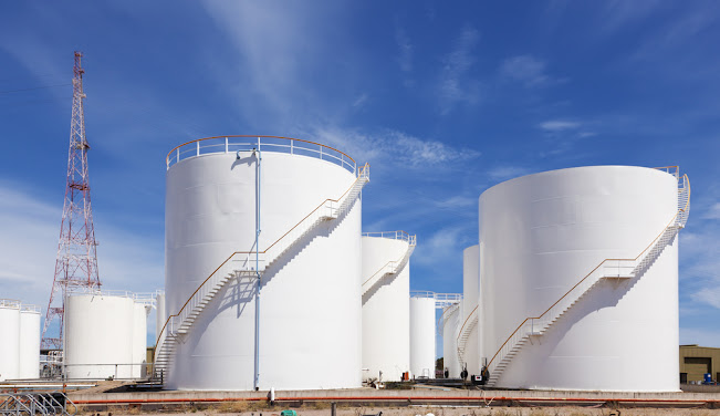
4.  Location of storage tanks relative to process units.
5.  Safe distances between units, tanks, storages, loading and any other facilities with respect to pipe rack.
6.  Location of the entrance and exit of process and utility lines, w.r.t. the unit limits.
7.  Variations in the site grade levels.
8.  Maximum and minimum size of pipe line that can be run on the pipe rack.
9.  Spacing between two pipes.
10. H.T cable routing above ground or rack or U/G.


Site Plan/Overall Plan

Site plan is the overall layout of the entire project. Site plan shows the locations of various units e.g. tank farm, flare area, utility area, loading/unloading area, various process units and pipe rack. For existing pipe rack major loop dimensions and additional structure provided to support it are also needed to review for new facilities / Pipe ways proposed next to it. In this document, the rack layout is developed by making various alternatives and in discussion with client and process licensor.

Plot Plan

This is a layout of a unit. The plot plan locates major technological structures including racks, buildings and all equipment. This will give the location of ISBL pipe rack. The location of this rack at B/L is crucial for connecting to OSBL pipe rack. The OSBL pipe rack overall layout is normally shown in the right plan drawing.

Process Flow Diagrams /P&IDs/UFDs

1. Process flow diagrams show the essential lines that connect process equipment. They provide insight to operating temperatures and identify the need for insulation.

2. Piping and Instrument diagrams indicate the complete flow systems necessary for plant operation, and include pipe sizes, valves, manifolds, and all piping and instrumentation details.

3. Utility distribution diagrams show the number and size of water, steam, condensate, gas, air, etc. headers and all equipment supplied by these headers, with necessary valves and piping connections in sequence to reflect site conditions. The utility mains generally run the whole length of the rack. These lines should be taken into account when estimating space requirements. This document is helpful during initial design of pipe rack.

There are various options available for construction material of pipe rack like

i) Steel Structure

ii) Precast concrete bents

iii) In-situ concrete

The decision between various options is to be taken by Civil, with Piping in loop, and is to be approved by client. Further development of rack layout is significantly affected by the option that has been selected for a project. Since the concrete pipe racks require structural members of larger size, hence, the spacing/ elevation requirements may have to be increased. Generally, in grassroot plants, concrete rack is preferred and in revamp jobs, steel may happen to be more construction friendly.


Rack layout

Rack layout shows the route of rack throughout the plant, elevation at different locations, spacing between the bents, width of rack, rack column i.e grid nos location and bridge location across the roads. Interconnection diagram along with the site plan (overall plan) is essential for development of rack layout.


Load data to Civil

This falls under two condition:

a) Project schedule allows for general development of design where P&ID at IFD stage are available prior to load being furnished to Civil. In this case the loads shall be made available based on actual requirements.

b) If project schedule does not allow, but similar project data is available then that can help in taking a decision on a standardized load data throughout, provided it is
acceptable to client. Client should be made aware that though standardization will help in schedule but may also lead to over design and same should be recorded.
While designing operating load, thermal / friction / guide loads, Anchor loads, wind loads,Seismic loads are taken into account.

  1. Sustain load
  2. Weight of piping valve with insulation
  3. Thermal load
  4. Load of thermal expansion of piping
  5. Dynamic load
  6. Load by vibration of piping, Wind, Earthquake
  7. Sustain load
  8. Liquid load by hydrostatic pressure test
Calculate the width of Pipe rack

w= (f X n X s) + A + B. 
     
f : Safety Factor
  • 1.5 if pipes are counted from PFD.
  • 1.2 if pipes are counted from P&ID.
n = number of lines in the densest area up to size 450NB.
  • 300 mm (Estimated average spacing)
  • 225 mm (if lines are smaller than 250 NB)
A : Additional Width for
  • Lines larger than 450 NB.
  • For instrument cable tray
  • For Electrical cable tray. 
s : 300 mm (estimated average spacing)
     225 mm (if lines are smaller than 250 NB)

B : future provision
  • 20% of (f X n X s) + A


    << READ OTHER INTERESTING POST >>


 PIPE RACK PIPING


       READ POST >>


   PIPING SUPPORTS


  READ MORE >>


EXPANSION LOOP CALCULATION


 READ MORE >>


 HEAT EXCHANGER


 READ POST >>


 TYPES OF PUMP


READ POST >>


     DISTILLATION COLUMN PIPING


       READ MORE >> 


     TYPES OF GASKET


        READ POST >>


        OIL & GAS PROCESS


       READ POST >>


   CHECKLIST FOR PIPING ISOMETRIC

    READ POST >>


     TYPES OF GASKET


        READ POST >>


Pipe Wall Thickness calculation

    READ MORE >>


    TYPES OF FLANGES

     READ MORE >>


   PDMS & E3D COMMANDS

      READ POST >>


TYPES OF STORAGE TANK


 READ POST >>


EQUIPMENT LAYOUT Basic engineering supplier provide the initial information for doing equipment layout work. Piping Department does layout s...

EQUIPMENT LAYOUT

  • Basic engineering supplier provide the initial information for doing equipment layout work. Piping Department does layout studies in consultation with process, civil, electrical, instrumentation, operations, maintenance and construction for preparing the equipment layout.
  • With the help of PFD, P&ID, Site Plan, Vendor data, Equipment Data sheets, Plant North, prevailing wind direction and below mentioned points, equipment general arrangement should be prepared to finalize overall plot size required, major structural requirement, pipe rack widths, access roads and widths etc. Plot Level and grading plan to be taken from Civil and incorporated in the Equipment Layout.
  • To start equipment layout ,one should have basic idea of flow sequence of raw material and finished product. The sequence of flow should start from one end near battery limit. This battery limit basis should be finalized on basis of overall site plan and interconnecting piping.
  • The major equipment's as per PFD and basic equipment list should then divided into sub system or blocks which consist of interconnected equipment's. Interconnection between various system to be studied. Once the interconnectivity is established , next step is to arrange equipment as per inter-distance and access requirement obtained from OISD-118 or Project specification.
  • Study should be required to find out which equipment should be elevated for gravity flow requirement, or which can be elevated for saving floor space, economy and other related advantages and disadvantages. Planning should be done for staircase location, fire and emergency exit and drop zone from the structure.


Various Factors to be considered to develop equipment layout :

  1. PROCESS REQUIREMENT
  2. LAYOUT SPACE AVAILABILITY
  3. EQUIPMENT SIZE
  4. UNDERGROUND FACILITIES REQUIREMENT
  5. PIPE RACK
  6. ROAD, ACCESSWAY, PAVING
  7. PLANT LAYOUT SPECIFICATION
  8. ECONOMIC PIPING
  9. COMMON OPERATION
  10. FUTURE EXPANSION


EQUIPMENT LOCATION PHILOSOPHY :
  • Process unit shall be located on high ground to avoid flooding.
  • process units should be located in block type layout for fire fighting purpose.
  • PIB, control rooms and substation shall be located at edge of unit adjacent to road at a safe distance from equipment.
  • Road access to be provided from all four directions to a process unit for effective fire fighting and dead ends to be avoided.
  • Equipment should be arranged alongside the rack as rack is consider main artery of a unit.
  • Wind direction: Equipment layout should be done considering prevailing wind direction to avoid travel of hydrocarbon/toxic gases.
  • Equipment in Process unit shall be arranged in a sequential order of process flow to minimize pipe run length.
  • Layout should allow easy access to all equipment and adequate space and access for piping and instrumentation.
  • Emergency escape route ,provide alternate escape routes from potentially dangerous areas subject to fire and hazards.
  • Equipment layout and plot plan is used to schedule erection sequence of plant equipment at grade or in structures which include rigging studies for large lifts, Cranes & Derricks.
  • Inter distance between equipment and various facilities to be in accordance with OISD-STD-118 & project specification & requirement.

Plant layout needs statutory approvals before implementation. Some of the statutory approving codes are:

1. Indian Factories Act
2. Indian Explosives Act
3. Petroleum Act
4. Central / State Pollution Control Board Law
5. Indian Electricity Rules
6. CIVIL aviation rule - National Airports Authority
7. Insurance Association of India - Fire Protection manual.
8. N. F. P. A. Code of Practice.

Following Design Data Required:
  1. Licensor/basic engineering supplier data : Capacity of process unit, indicative equipment approximate dimension, Block flow diagram, Utility requirement.
  2. Process Data : PFD, P&ID , Process data sheet, Hazardous nature of unit, Operating philosophy.
  3. Civil Data : Plot Level, Grading plan.
  4. Metrological Data: Wind direction, Rainfall
  5. Electrical data: Electrical hazardous area classification, substation size.
  6. Instrumentation data : Analyzer house requirement, PIB sizes.
  7. PDP data : Site plan & ISBL/OSBL battery limit interface location.
  8. Statutory requirement : OISD,PESO,IBR,OSHA etc.


   << READ OTHER INTERESTING POST >>


     DISTILLATION COLUMN PIPING


       READ MORE >> 


 PIPE RACK PIPING


       READ POST >>


   PIPING SUPPORTS


  READ MORE >>


EXPANSION LOOP CALCULATION


 READ MORE >>


   CHECKLIST FOR PIPING ISOMETRIC

    READ POST >>


     TYPES OF GASKET


        READ POST >>


Pipe Wall Thickness calculation

    READ MORE >>


    TYPES OF FLANGES

     READ MORE >>


   PDMS & E3D COMMANDS

      READ POST >>


TYPES OF STORAGE TANK

     READ POST >>


HEAT EXCHANGER 


READ POST >>


 TYPES OF PUMP


READ POST >>


PUMP PIPING


    BUTTERFLY VALVE            Butterfly valves are quarter-turn valves that are popular for on-off or modulating services. They are lightwe...

  BUTTERFLY VALVE

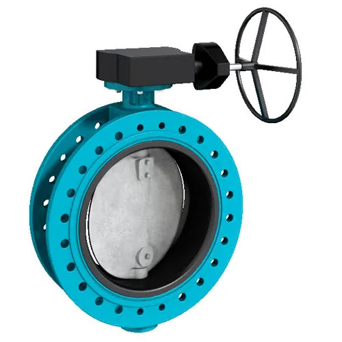
           Butterfly valves are quarter-turn valves that are popular for on-off or modulating services. They are lightweight, have a small installation footprint, lower cost, quick operation, and are available with large orifice sizes. The “butterfly” is a disk connected to a rod. When the valve opens, the disk rotates to allow fluid to pass through. It closes when the rod rotates the disc by a quarter turn to a position perpendicular to the flow direction. 


3 Main Butterfly Valves Types: 

       1) Zero-Offset Butterfly Valves
           Concentric or Rubber Seated are other names for the Zero-offset Design. Zero-offset means there is no offset by the stem of the valve. the valve seals via interference along the disc edge at the stem between disc and the rubber seat.
          The rubber seated valves has the lower (up to 250 psi) and withstands heat up to 400°F. Its rubber seat encases the body to prevent contact with material which maintains the purity of media.
  

       2) High-Performance Double Offset Butterfly Valves:
            This type of valve is refereed to as double offset because the offset is in two places, at the line of the disc seat/body seal, and the bore. Off-center positioning increases durability for the seal. High-performance valves tolerate pressure up to 1440 PSI and temp up to 1200°F.

       3) Triple Offset Butterfly Valve:
           The best type of butterfly valve for high-pressure systems is the triple offset butterfly valve. This valve is most advanced with Lower emissions and is designed to work with various environments. Its heat tolerance is 1200°F as it can withstand 1480 psi.

working principle

The construction of a butterfly valve is relatively simple, with the rotation of the valve disc controlling the fluid flow. In the closed position, the disc blocks the valve bore while in the open position, the disc is oriented perpendicular to the flow direction to allow flow. Butterfly valves generally provide bi-directional flow and shutoff capability. However, they are not full-bore, which renders them unsuitable for pigging or swabbing. The body material is ductile iron with an epoxy powder coat on both internal and external surfaces. The valves are typically operated by handwheels, gears, or actuators, or a combination thereof, according to the specific application requirement and technical specifications.


Butterfly valve parts

Below are the major butterfly valve components:

  • Valve Body
    The valve body fits between the pipe flanges - the most common end connection types being flanged, double lug, and wafer types.
     
  • Disc
    Attached to the valve body is the disc that functions as a gate that stops or throttles fluid flow; it can be considered equivalent to a gate in a gate valve, or a ball in a ball valve. The disc is typically bored to receive the stem, or shaft. There are many variations in disc design, orientation, and material in order to improve flow, sealing, and/or operating torque. 
     
  • Seat
    Lining the internal valve body is a strong elastomer or metal anti-leak seal that secures the disc in place in the closed position in order to achieve complete shutoff. stainless steel weld filled and microfinished integral body seat ensures a corrosion and erosion resistant seat face. 
     
  • Stem
    The valve shaft, often also referred to as the stem, is the component that connects the disc to the actuation mechanism and transmits the torque through itself.
     
  • Seals
    Seals are present at multiple interfaces within the valve to either ensure a tight seal during operation or to isolate the process media from the valve’s internal components for a more flexible and cost-efficient design.

Sealing on seat face is ensured by a continuous T-profile resilient sealing ring which is held on the periphery of the disc by a retaining ring, preventing the sealing ring from rolling out. In the closed position, the sealing ring is pressed against the seat face, providing a tight seal on both the upstream and downstream ends. In the open position, the sealing ring is completely unstressed due to the double eccentric disc design.

Advantages of butterfly valves

Depending on the application, butterfly valves can offer significant advantages over other types of valves, especially for dimensions over DN 200 (200 mm) in size:

  1. Lightweight and Compact: With a compact design and a smaller face to face dimension, butterfly valves have a considerably less installation footprint and offer savings in the form of lower installation costs including labour cost, equipment, and piping support.
     
  2. Low Maintenance Requirements: An inherently simple, economic design that consists of few moving parts, and hence fewer wear points, significantly reduces their maintenance requirements.
     
  3. Fast Acting: A 90° rotation of the handle, or the actuation mechanism, provides a complete closure or opening of the valve. However, with larger butterfly valves, a gearbox is often required as part of the actuation mechanism which reduces the operational torque and simplifies the operation of the valve but comes at the expense of speed.
     
  4. Low Cost: Owing to their simple design, butterfly valves require less material and are simpler to design and manufacture and are often the more economical choice compared to other valve types. 
                                                                                                                                                          

       << READ OTHER INTERESTING POST >>


   PIPING SUPPORTS


  READ MORE >>


EXPANSION LOOP CALCULATION


 READ MORE >>


     DISTILLATION COLUMN PIPING


       READ MORE >> 


   CHECKLIST FOR PIPING ISOMETRIC

    READ POST >>


 PIPE RACK PIPING


       READ POST >>


     TYPES OF GASKET


        READ POST >>


        OIL & GAS PROCESS


       READ POST >>


Pipe Wall Thickness calculation

    READ MORE >>


    TYPES OF FLANGES

     READ MORE >>


 HEAT EXCHANGER


 READ POST >>


 TYPES OF PUMP


READ POST >>