PIPING-KNOWLEDGE has useful guide for piping engineers. including piping layout , piping supports , codes and standards, software learning like aveva E3d , Pdms , Caesar II. site contain different piping layout .It also content video animations of valves and oil and gas refining process.site has overal piping engineering guide which is useful for piping engineer.

SCRUBBER Scrubbers remove unwanted gases and particulate matter from industrial smokestacks before they enter the atmosphere. The two main t...

SCRUBBER

Scrubbers remove unwanted gases and particulate matter from industrial smokestacks before they enter the atmosphere. The two main types of scrubbers wet scrubbers and dry scrubbers can reduce up to 90 percent of emissions that contribute to smog and acid rain.


WET SCRUBBER:

 Wet scrubbers are utilized when a gas stream becomes contaminated by particulate or a gas, or a combination of both. Some gas pollutants could be ammonia, chlorine, or sulfur compounds. In the wet scrubber, these gasses will be dissolved or absorbed into the scrubbing liquid. The liquid many times is water, but can vary depending on the pollutant. In Industrial exhaust systems these harmful gasses or particulates must be removed to ensure optimal performance and compliance. Particulate matter is microscopic or liquid matter that finds its way into the gas stream. When the liquid comes into contact with the dust particulate, the heavier and coarser particles are washed out and carried down to make contact with the mist eliminator pads.


DRY SCRUBBER:

A dry scrubber or dry scrubber system is one type of scrubber that is used to remove harmful materials from industrial exhaust gases before they are released into the environment. Dry scrubbers are the type most commonly used in plants today, and they utilize a collection of dry substances to remove acidic gases that contribute to acid rain.

Dry scrubbers work similarly to other scrubbers. The system sprays a collection of dry reagents into an exhaust stream. These chemicals can react differently depending on which material they are specifically targeting for removal. Some of these materials neutralize harmful pollutants in the stream through a chemical reaction, while others cause a material to react and turn into a different substance. That substance then falls out of the gas stream or is caught in a particle screen.

VENTURI WET SCRUBBER:

Venturi scrubbers are perfect for collecting fine particulate and liquid mists. Using the differential between high velocity gases and free-flowing water to create contaminant-entrapping droplets, these scrubbers can suspend and contain a multitude of pollutants in your system. By maintaining high gas velocities and turbulence in the throat of the design you can achieve high collection efficiencies, ranging from 90% to 99% for particles with a diameter larger than 1 µm and greater than 80% for submicron particles.


PACKED TOWER WET SCRUBBER:

Packed tower scrubbers, also called packed bed or packed column scrubbers, are best for getting rid of gas phase emissions like sulfur dioxide or other odors and acids. By chemical scrubbing contaminants from your gas streams, these types of scrubbers, when designed correctly, can remove toxic or otherwise harmful emissions from gas streams and exhaust clean air into the environment. Internal packing within the scrubber provides a large wetted surface area that forces a close-contact interaction between the scrubbing liquid and the contaminated airflow. The scrubbing liquid then either absorbs or reacts with the contaminants, effectively removing them from the air. The typical collection efficiency range is from 90% to 99%, with that efficiency becoming greater than 99% for select pollutant systems. Packed tower scrubbers are less effective when dealing with particulate matter control, as high concentrations of dust can easily clog the bed of the tower. 


    Advantages

  • Can handle flammable and explosive dusts with little risk
  • Provides gas absorption and dust collection in a single unit
  • Provides cooling of hot gases
  • Compact; can often be retrofitted into existing collection systems
  • Corrosive gases and dusts can be neutralized


     Disadvantages

  • High potential for corrosion problems
  • Collected particulate may be contaminated and unrecyclable
  • Protection against freezing required. Certain streams may require reheating to avoid visible plume
  • Disposal of waste sludge can be very expensive
  • Requires makeup water to replace purged liquid and disposed sludge


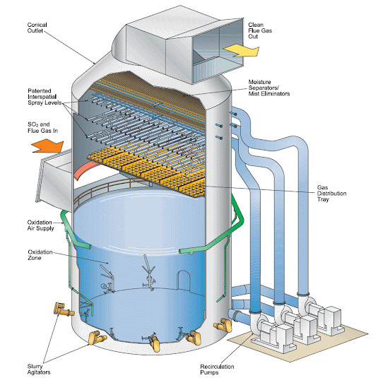
      WORKING OF SCRUBBER:


            << READ OTHER INTERESTING POST >>


   PIPING SUPPORTS


  READ MORE >>


EXPANSION LOOP CALCULATION


 READ MORE >>


     DISTILLATION COLUMN PIPING


       READ MORE >> 


 PIPE RACK PIPING


       READ POST >>


     TYPES OF GASKET


        READ POST >>


        OIL & GAS PROCESS


       READ POST >>


    PDMS & E3D COMMANDS

      READ POST >>


TYPES OF STORAGE TANK


 READ POST >>


 STEAM TRAP   A  steam trap  is a device used to discharge condensates and non-condensable gases with a negligible consumption or loss of li...

 STEAM TRAP 


steam trap is a device used to discharge condensates and non-condensable gases with a negligible consumption or loss of live steam. Steam traps are nothing more than automatic valves. They open, close or modulate automatically.

The three important functions of steam traps are:

  • Discharge condensate as soon as it is formed (unless it is desirable to use the sensible heat of the liquid condensate)
  • Have a negligible steam consumption (i.e. being energy efficient)
  • Have the capability of discharging air and other non-condensable gases.

TYPES OF STEAM TRAP:


  1. Mechanical traps. These remove condensate through the use of the mechanical properties of steam vs condensate. Since liquid is denser than the steam it will travel to the bottom of the system. Mechanical traps will have a bucket or float that rises and falls in relation to condensate level and this usually has a mechanical linkage attached that opens and closes the valve. Mechanical traps operate in direct relationship to condensate levels present in the body of the steam trap. Inverted bucket and float traps are examples of mechanical traps. Float traps can have a mechanical linkage or can seal the trap through use of the float itself.


2. Thermostatic traps. These remove condensate through the temperature  difference of steam vs the liquid phase. The valve is driven through expansionand contraction of an element that is exposed to the heat from steam or condensate.  These traps take a temperature drop below the saturation curve to open and   remove condensate. These traps can perform this by a filled element or bellows or bimetallic element.


3.Thermodynamic traps. These operate on the dynamic principals of steam         vs condensate and the use of Bernoulli’s principle. When condensate               released through an orifice the speed increases and a pressure drop                 occurs. This will flash steam to create higher pressure to close a valve             (disc) or slow the discharge speed of the trap.


Considerations for steam trap selection

Air venting

At ‘start-up’, i.e. the beginning of the process, the heater space is filled with air, which unless displaced, will reduce heat transfer and increase the warm-up time. Start-up times increase and plant efficiency falls. It is preferable to purge air as quickly as possible before it has a chance to mix with the incoming steam. Should the air and steam be mixed together they can only be separated by condensing the steam to leave the air, which must then be vented to a safe place. Separate air vents may be required on larger or more awkward steam spaces, but in most cases air in the system is discharged through the steam traps. Here thermostatic traps have a clear advantage over some types of trap since they are fully open at start-up. Float traps with inbuilt thermostatic air vents are especially useful, while many thermodynamic traps are also quite capable of handling moderate amounts of air. However, the small hole in fixed orifice condensate outlets and the bleed hole in inverted bucket traps both vent air slowly. This could increase production times, warm-up times, and corrosion.

Condensate removal :

Having vented the air, the trap must then pass the condensate but not the steam. Leakage of steam at this point is inefficient and uneconomical. The steam trap has to allow condensate to pass whilst trapping the steam in the process. If good heat transfer is critical to the process, then condensate must be discharged immediately and at steam temperature. Waterlogging is one of the main causes of inefficient steam plant as a result of incorrect steam trap selection.

Plant performance:

When the basic requirements of removing air and condensate have been considered, attention may be turned to ‘plant performance’. Simply put, unless specifically designed to waterlog, for a heat exchanger to operate at its best performance, the steam space must be filled with clean dry steam. The type of steam trap will influence this. For instance, thermostatic traps retain condensate until cooled to below saturation temperature. Should this condensate remain in the steam space, it would reduce the heat transfer area and the heater performance. The discharge of condensate at the lowest possible temperature may seem very attractive, but generally most applications require condensate to be removed from the steam space at steam temperature. This needs a steam trap with different operating properties to the thermostatic type, and this usually means either a mechanical or thermodynamic type trap.


Before choosing a particular steam trap it is necessary to consider the needs of the process. This will usually decide the type of trap required. The way in which the process is connected to the steam and condensate system may then decide the type of trap preferred to do the best job under the circumstances. Once chosen, it is necessary to size the steam trap. This will be determined by the system conditions and such process parameters as:


Maximum steam and condensate pressures.
Operating steam and condensate pressures.
Temperatures and flowrates.
Whether the process is temperature controlled.


       << READ OTHER INTERESTING POST >>


   PIPING SUPPORTS


  READ MORE >>


EXPANSION LOOP CALCULATION


 READ MORE >>


     DISTILLATION COLUMN PIPING


       READ MORE >> 


   CHECKLIST FOR PIPING ISOMETRIC

    READ POST >>


 PIPE RACK PIPING


       READ POST >>


     TYPES OF GASKET


        READ POST >>


        OIL & GAS PROCESS


       READ POST >>


Pipe Wall Thickness calculation

    READ MORE >>


    TYPES OF FLANGES

     READ MORE >>


 HEAT EXCHANGER


 READ POST >>


 TYPES OF PUMP


READ POST >>


  Insulation and Heat Tracing THERMAL INSULATION Insulation is defined as any material that resists the transfer of heat energy. The pur...


Insulation and Heat Tracing


THERMAL INSULATION

Insulation is defined as any material that resists the transfer of heat energy. The
purpose of thermal insulation is therefore either to keep heat confined in the
mechanical system or to keep it excluded from the system by preventing or resisting
heat transfer.


The four functions of insulation for hot piping and equipment are:

Conserve heat
Protect personnel
Maintain temperature for process control
Preventing fluid freezing in cold climates

There are two basic types of thermal insulation:

Mass Insulation
Reflective Insulation

Mass insulation is made up of small pockets or spaces that trap air or gases that are
separated by solid structures. The voids provide resistance to the heat transfer process.


Mass type insulation includes:

Calcium Silicate which is a compound of lime and silica with reinforcement fibers molded into pipe shapes, sizes, including elbows. It is used in applications with system
temperatures up to 1200
° F. Even though the dust caused by working with Calcium
Silicate may be a safety concern, the insulation material is more rigid and more durable than other insulating materials.


Mineral-Fiber Insulation which is available in both blankets and shapes. It is made from rock and slag fibers which have been bonded together. It is used in applications with system temperatures to 1500
° F.


Glass Type insulation is available in several forms including glass wool, fiber board,
and felted glass fibers. Some forms of glass type insulation are designed for
temperature services up to
1000
° F.


Reflective insulation materials include Aluminum or Stainless Steel sheets or foil
used for the construction of reflective blankets. The temperature limits for the
aluminum materials are approximately 
1000° F. The stainless steel materials are
adequate for temperature ranges up to 
1500° F.

The inner layer of insulation is normally installed as the insulating material and the
outer metal cover is installed to protect the insulation from damage. Insulating

jackets or protective covers are usually aluminum or stainless steel sheeting.

Personnel protection insulation is normally provided on hot piping that is not required
to be insulated for design requirements but which can be reached by a person
standing on the ground or the nearest platform. Normally personnel protection
insulation is provided on uninsulated piping with operating temperatures above
140° F and within feet of the ground or feet from the platform edges or ladders.

Flange connections typically have removable sections or a flexible blanket assembly
placed over the joint which permit easy future removal. Nameplates, code plates,
pipe plugs and blind nipples should be left exposed or have a small removable
section of insulation placed over them.


Removable insulation covers should be:

One piece construction wherever possible
Fabricated in multiple sections when a one piece cover exceeds 60 pounds total
weight
Constructed with edges that butt tightly together to minimize heat loss and
provide a cover of neat finished appearance
Resistant to water, oil, and steam
Constructed to prevent the entry of fluids or moisture into the internal insulating
material
Constructed to fit snugly around the contours of the component being insulated,
including valves, flanges, straight pipe, and fittings
Constructed with no sharp edges or protrusions on the outer surface


Equipment Insulation
Equipment insulation blocks, boards, or blankets are normally attached to the equipment surface with joints staggered and the edges tightly butted and sealed with insulation cement, except in those cases where expansion or contraction joints are provided.

Insulation is normally attached by one of the following methods:

Vendor furnished and installed attachment devices
Welded attachments installed to secure the insulation
Stainless steel, copper coated steel, or aluminum steel wire
Stainless steel or aluminum bands


Insulation Jacketing and Surface Finish

Prior to the installation of the insulation jacketing, the installed insulation must be
verified to be complete and properly installed. Joints provided for thermal expansion
or contraction must be filled with insulating mastic material or mineral fiber batting.
The jacketing on both piping and equipment insulation should be fastened with
bands wherever possible. When bands cannot be used due to the piping or
equipment configuration, the jacketing may be secured with sheet metal screws.

Jacketing joints and openings must be sealed with a caulking material when the
insulation system contains a moisture or vapor barrier and the system is installed
outdoors. Removable insulation jacketing must overlap adjacent pipe by an amount
equal to the insulation overlap.


HEAT TRACING

Four typical heat trace systems include:

Electrical Heat Trace
Bare Steam Trace
Heat Transfer Cemented Steam Trace
Hot Water


Electrical heat trace systems are installed by simply wrapping electrical trace around
piping and equipment to provide mild winterization protection. Some high
temperature piping systems require the use of a layer of insulation between the pipe
and heat trace to avoid damage to the heat trace.
Bare Heat Transfer Cemented Steam Trace and Hot Water Trace systems are
applied by placing and banding tubing along the piping runs and looping the tubing
around equipment and valves. The function of the steam trace is to maintain the
process fluids at temperature levels that provide proper flow characteristics.


    << READ OTHER INTERESTING POST >>


 PIPE RACK PIPING


       READ POST >>


   PIPING SUPPORTS


  READ MORE >>


EXPANSION LOOP CALCULATION


 READ MORE >>


 HEAT EXCHANGER


 READ POST >>


 TYPES OF PUMP


READ POST >>


     DISTILLATION COLUMN PIPING


       READ MORE >> 


     TYPES OF GASKET


        READ POST >>


        OIL & GAS PROCESS


       READ POST >>


   CHECKLIST FOR PIPING ISOMETRIC

    READ POST >>


     TYPES OF GASKET


        READ POST >>


Pipe Wall Thickness calculation

    READ MORE >>


    TYPES OF FLANGES

     READ MORE >>


   PDMS & E3D COMMANDS

      READ POST >>


TYPES OF STORAGE TANK


 READ POST >>